Bringing back my Amiga 500+ from the Varta grave
This is my personal account of how I got my Amiga 500+ running again.
This isn't meant to be a complete repair guide. I'm sharing it because I couldn't find much info about the exact problems I faced. I hope it helps someone with a similar board, or at least encourages you not to give up if your A500+ only shows a green screen.
A Green Screen and a Bad Assumption
After about 15 years of slumber, I dug out my original Amiga 500+ from the loft to relive some old games I loved as a teenager. I duly plugged everything in, flicked the switch on the foot warmer of a power supply, and... no friendly "Insert Disk" screen, just a green screen. I checked the connectors and removed the extra 1MB Chip RAM expansion, but nothing changed. Like many fellow Amiga 500+ owners, I was about to go down the Varta battery hellhole...
After searching online, it seemed the Amiga's early startup failed due to a possible memory error. Those flashing colours at startup indicate tests the Amiga is running, and the green screen indicates a Chip RAM/startup memory failure. I assumed it was a bad memory chip. I noticed a little green scum around the battery legs, but didn't think too much of it. I pushed on all the socketed chips in the vain hope that one was loose, but nothing changed that green screen. The memory chips looked fine - no visible damage. So I made a note of the parts and ordered some new ones from eBay, then packed the Amiga away again, waiting for me to get round to fixing it.
About five years later, after playing around with my Amiga 1200, I had an urge to bring back my old friend, the Amiga 500+, from the dead. I started doing some research and quickly realised the onboard battery was notorious for destroying old computer hardware. I opened my Amiga 500+ up again and snipped off the old battery.
 The original Varta battery area before the real cleanup began. At first glance, it did not look too terrible, but
the damage had already crept into the surrounding traces.
The original Varta battery area before the real cleanup began. At first glance, it did not look too terrible, but
the damage had already crept into the surrounding traces.
I had heard of people using Amiga PCB Explorer (www.amigapcb.org) to trace out parts of the Amiga motherboard, so I loaded it up and started studying the layout around the battery. In my searches, I also came across a replacement ROM called DiagROM (www.diagrom.com) that had a good reputation for booting faulty Amigas into a custom test suite, outputting diagnostic data to the serial port as the machine started booting, so you could still use it for testing if the display wasn't working.
DiagROM Had Nothing to Say
I ordered a ROM chip with this burned onto it, and when it arrived, I popped it into the Amiga, plugged the serial cable I normally used with Amiga Explorer into my PC's serial port, and loaded PuTTY with the correct serial settings. And... nothing. No output at all. Whatever was wrong with the computer was bad enough that even DiagROM couldn't get a word out of it, which told me this was probably more than a simple display problem.
I went back to the motherboard, cleaned the area thoroughly with alcohol and a toothbrush, and used a multimeter in continuity mode to trace the connections from the real-time clock chip's pins to the surrounding components on the board. I'm not too confident with soldering and electronics, though I always had big ambitions of building my own computer gadgets. I was really surprised when I managed to find a broken trace.
I grabbed some thin cable and soldered one end onto pin 1 of U12 and the other end to the end of the broken trace, a resistor marked as R113. I quickly plugged the power cable back in, tentatively flicked the power switch, and instantly saw some serial output from the Amiga! I was pretty happy with myself. That was the first time I had actually fixed something instead of making it worse!
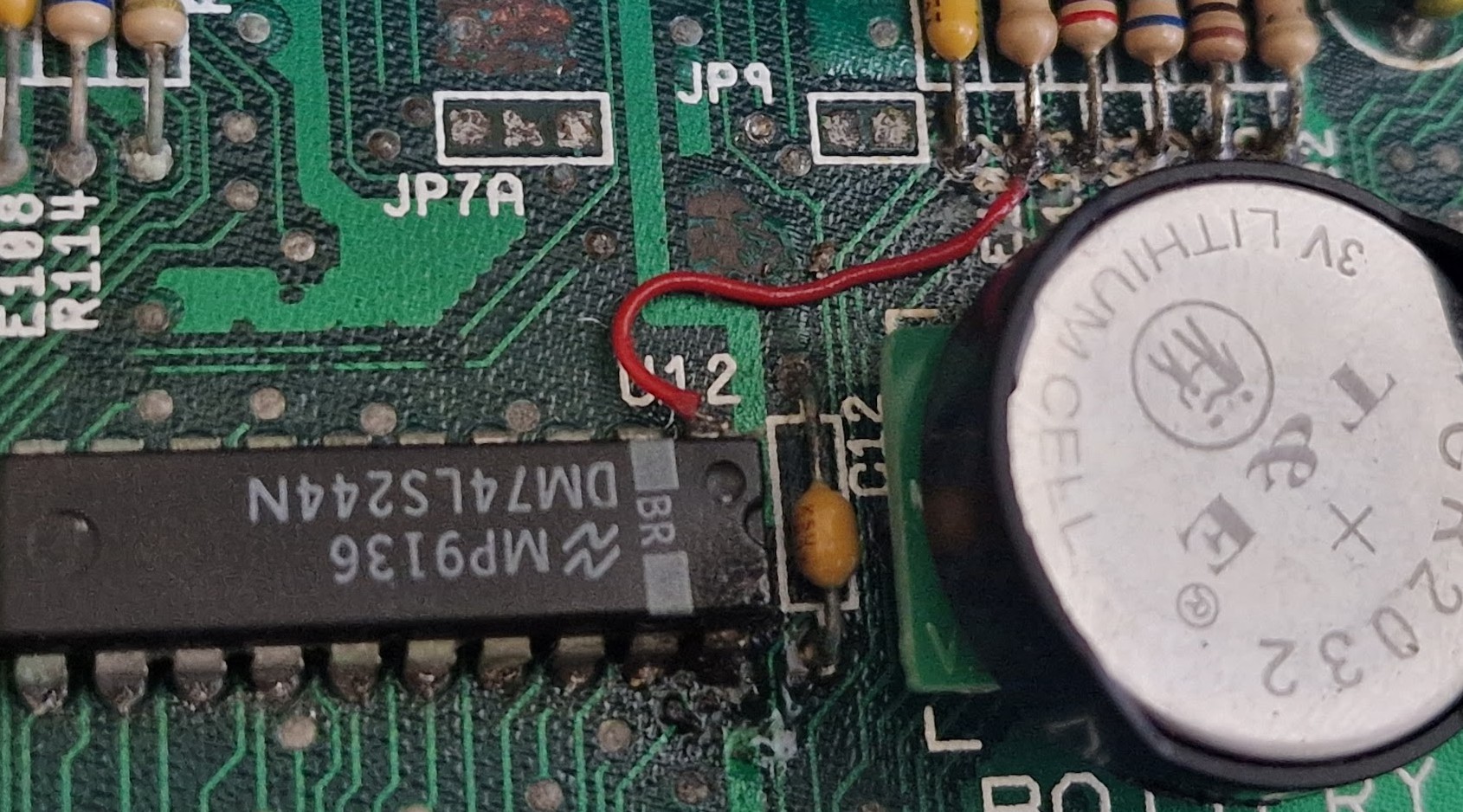
The jumper wire repair that brought the board back to life enough for DiagROM to start producing serial output.
Back From the Dead, Mostly
Once the machine was booting, I fitted a replacement coin-cell battery holder from AmigaKit. This had a diode fitted to stop the Amiga from trying to charge the coin-cell. I didn't like the look of some of the capacitor legs around the battery, so I thought now was the best time to replace them all.
After a bit of testing, I found some of the keys on the keyboard were dead. I took the keyboard apart and tried cleaning the contacts, but no change. I ordered a new membrane for the keyboard, one of those newer thin PCB designs, and that got the keys working again.
While I had the keyboard apart, I took the opportunity to give the keys a good clean by removing them (watch out for flying springs!) and soaking them in warm soapy water along with the grimy plastic keyboard frame. I also gave the old case a good soap bath, cleaning off decades of grime.
Once everything was squeaky clean again, I put it all back together and got down to some serious laps on Lotus Esprit Turbo Challenge. Everything worked, which was more than could be said for some of my original disks.
I bought a floppy disk swapper that could swap the internal floppy drive for the external drive, and I replaced the external floppy drive with a Gotek drive, letting me boot up games from disk images stored on a USB stick. I wanted to keep the old floppy drive in there as it still seemed to work with some of my disks, and I'm pretty nostalgic for the sound of the real floppy disk grinding away.
The Gotek is brilliant and even has a speaker to emulate the drive sounds, but nothing beats the real thing. At that point, the Amiga 500+ felt fully fixed and cleaned, ready to download and play some mod tunes with Imp3, and its excellent ImpBox parallel port dongle.
The only thing it needed to make it more practical was an HDMI upgrade using RGB2HDMI, which I popped in there and only rarely looked back (you can't beat the glow of a proper CRT monitor).
The Clock Still Wasn't Ticking
And that's how it stayed for well over a year. Recently, I pulled the Amiga 500+ out again, loaded Workbench, played around with it and found it couldn't detect the built-in real-time clock. I checked the coin-cell battery, and it was still good, so I went back to Amiga PCB Explorer to hunt for another broken trace.
I researched a bit more about battery damage and found people recommending neutralising the alkaline that leaches from the battery with vinegar, then using alcohol to clean the vinegar off. So I pulled it apart once more and attacked the battery area again, trying to remove any green battery scum I could find. Some of it was pretty well embedded in the motherboard and was hard to remove without damaging the board. I did what I could, cleaned it up, and used an air blower to blast out any remaining liquid from under the components.
I then started tracing each pin on the clock chip to make sure there were no more broken traces hiding around that part of the circuit. Nothing. I noticed some of the clock traces were going to the Gary chip, so I popped that chip out and looked for some telltale green battery scum, but nothing - it had survived with no damage. So I gave the pins a quick clean and popped it back in. I looked up some other common faults with the clock chip and whipped out my cheap oscilloscope and checked the crystal signal was working - all looked good there. I then went down a bit of a rabbit hole, deciding that some data line signals didn't look clean or were a bit low-voltage. To be honest, I was enjoying the process - I was finding it a nice break from my other daily chaos.
The 5V Rail That Wasn't 5V
It was only the next day that I decided to go back to basics and check the power rails to the clock. The ground pin was perfect, but then I noticed Amiga PCB Explorer showing the 5V connection coming from a bundle of components right next to where the battery had leaked.
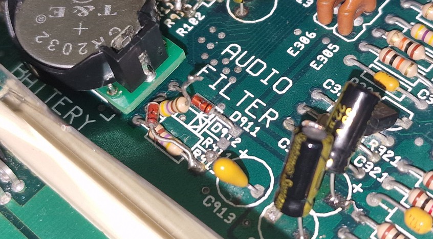
This part of the board had "AUDIO FILTER" silkscreened on it, and since the audio filter was working, I had largely overlooked it. It turns out that this part of the board is also responsible for keeping the rechargeable battery topped up via the original 12V charging path, while also supplying 5V to the clock when the Amiga is powered on, and backup battery power when the Amiga is switched off.
To be honest, how this actually works is out of my league, but it was interesting to note that this area appeared to have a factory patch in which the diode for D912 was moved to connect it to one side of R913. No idea what this does, but I left it well alone.
I turned the machine back on and was really surprised to find the 5V supply to the clock was actually around 10V! I could have kicked myself for not checking that first. I'm not sure if this 10V was from adding the coin cell in place of the original battery. I checked that the coin-cell holder had the diode fitted to stop back-charging, and it did, but I also noted it was still 10V with the coin-cell holder removed.
I traced the circuit and saw a connection to the 12V rail through R911, which I assumed was part of the original battery-charging circuit. I am far from being an electronics expert, so treat my findings with caution, but as the coin-cell holder already had a diode and did not need charging, I decided to lift one leg of R911 and leave it disconnected.
Result: The RTC Lives Again
I checked the voltage for the real-time clock, and it was now around 5V - result! I loaded up "Versatile Amiga Test program", asked it to check for the real-time clock, and it found it straight away.
R911 with one leg lifted after tracing the RTC Vcc line back to the original battery-charging circuit. On this board, that brought the RTC supply back down to around 5V.
After all this probing and prodding, the lesson was obvious: check the supply voltage first, but I was well chuffed with myself for finally having a working real-time clock. I saved a date and time to it, turned off the Amiga for about 30 minutes, turned it back on, loaded the real-time clock time, and it still had the correct time!
To double-check, I loaded Amiga Explorer, connected it to my PC, set the time to match my PC clock, made sure it was saved to the real-time clock, and turned off the Amiga. I checked it the next day, and it was nearly identical to the PC clock, only about 2 to 3 seconds out just by eyeballing the time. I did think about adjusting the variable resistor for the clock on the Amiga board to perfect the time, but really, I can live with a few seconds lost per day.
I'm not sure if the real-time clock on this Amiga ever worked. I remember when I was young and playing around with it, the time never seemed to survive the power cycle, but I didn't really care then. Who needs a clock when you've got games to play?
Overall, I'm happy to consider my old friend fully fixed, with hopefully no more battery goo left to cause further damage. Maybe someday I will come back and do a neater job of the jumper wire, shaping a thin piece of wire to follow the original trace more closely, but I do not want to risk damaging it any further right now.
A Repair, Not a Recommendation
I am not recommending that anyone simply lift R911. This fixed my board because the real-time clock Vcc line was being pulled far too high. Check the schematic, check your own board revision, and measure the real-time clock supply first.
I'm listening to some mods via Imp3 as I type this, and they play perfectly and sound great. Not that I need a working real-time clock to listen to some top Amiga tunes, but nevertheless, I'm very happy with the outcome.
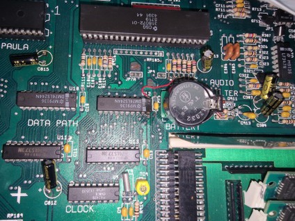
Final image showing the fixes applied to the Amiga 500 Plus board.